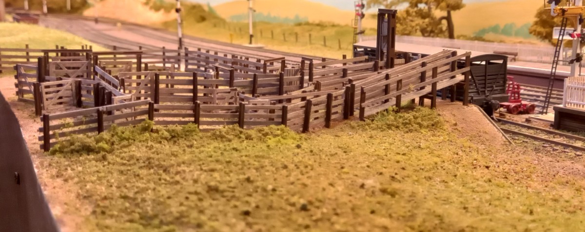
Modelling in a small space: Tarawangan trucking yard completed.
This project has been time-consuming and challenging but, ultimately, I am satisfied with the result. I relied heavily on Stephen Ottaway’s comprehensive review of prototype trucking yards in the Australian Journal of Railway Modelling, issue 13. I recommend it to anyone considering building a model. This is the first project that I have recorded from start to finish in parallel with construction. https://youtu.be/775mHW6Cj7k
Modelling in a small space: Tarawangan trucking yard progress.
Upper and lower sheep ramps and forcing yards almost complete. P-gate and frame for cattle ramp in place.All swing gates are hinged, so open and close. P-gate is fixed.
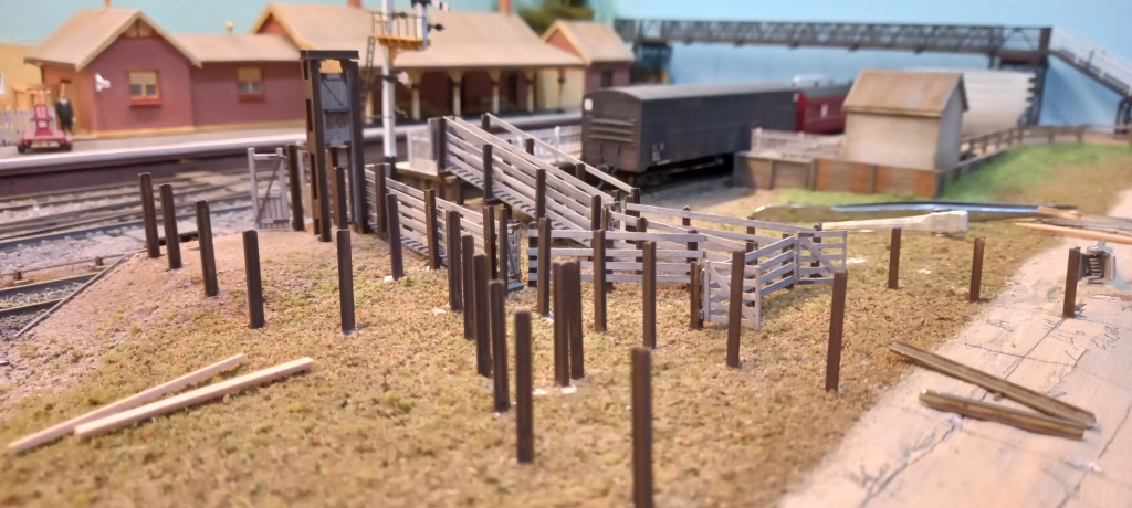
Modelling in a small space: a trucking yard for Tarawangan
The Tarawangan crew has begun work on a trucking yard. Early activity has centred on fabricating stock races and associated furniture. Nothing yet set in place – just stacking items as fabricated. More to follow.
Upper sheep race and working platform on right. Cattle race and lower sheep ramp in centre. Limit of unloading bank on left.
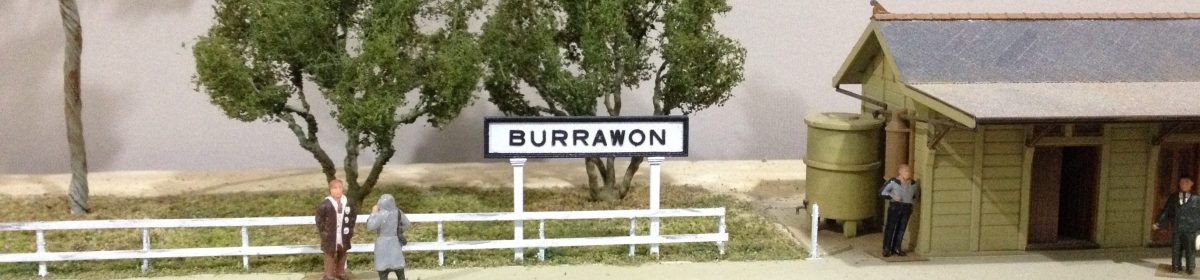
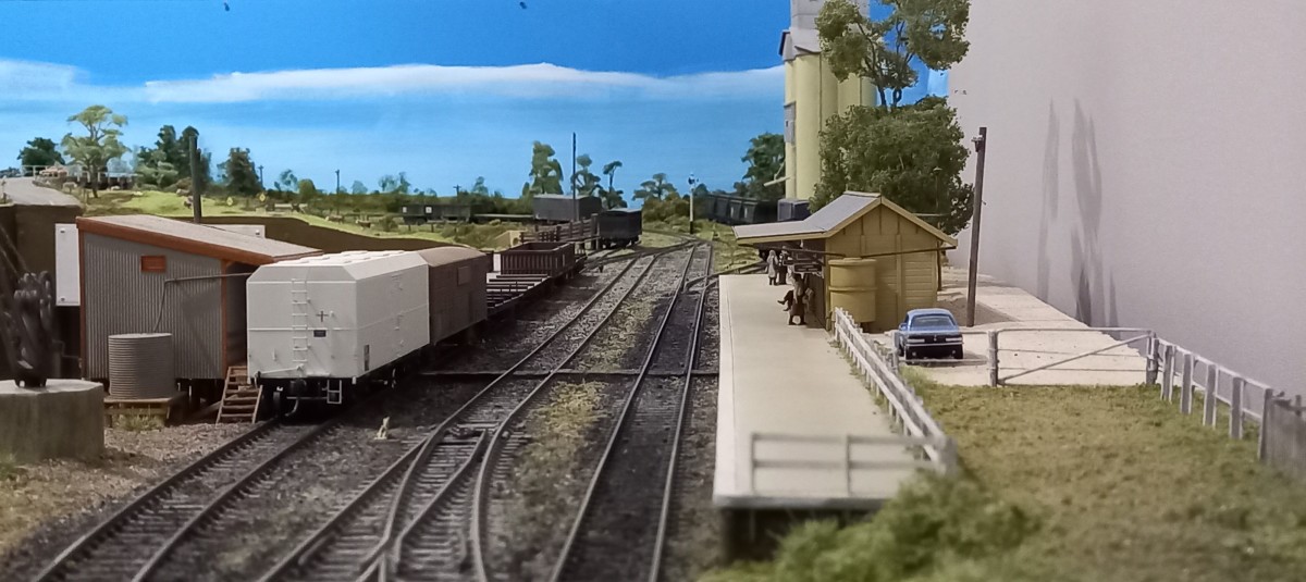
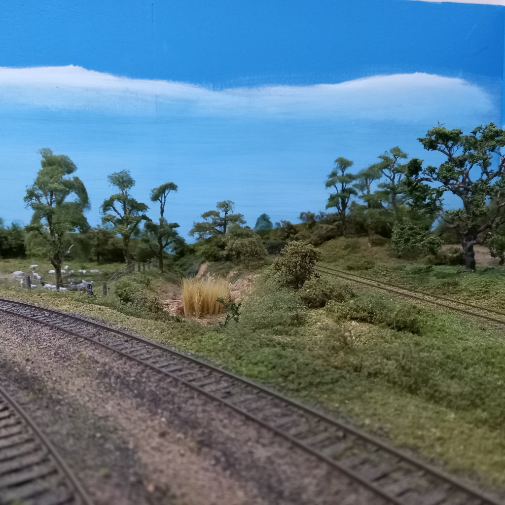
Modelling in a small space: a look at the scenes that contribute to the Burrawon diorama.
This short video outlines the mini scenes that contribute to the Burrawon station diorama. The key aim of the diorama is to convey the sense of space that is typical of rural settings. The scenery, structures and details within each scene are described. As an aside, the layout may be set in the early 1980’s, and it may still use DC, but that doesn’t mean that everything Burrawon is so 20th century. Recent concessions to the 21st century include adopting JMRI OperationsPro to generate train consists for operating sessions and, in the case of this video, embracing text to voice technology.
After assembling a list of detail items for the layout, I went online to place an order. I was taken aback at how fast and big the total grew, so I reviewed what I really needed vs what I wanted and trimmed the order. Nonetheless, the bill for what are minor detail items got me thinking about what I can reasonably make vs what I cannot. In truth, I prefer to make as much as I can because I enjoy scratchbuilding, and I have the time. Also, I can maintain a fairly uniform ‘standard’ of models on the layout which I think helps a layout look more convincing. Another reason I choose to scratchbuild is that I can use scale lumber for wooden items, and I prefer using wood to model wood.
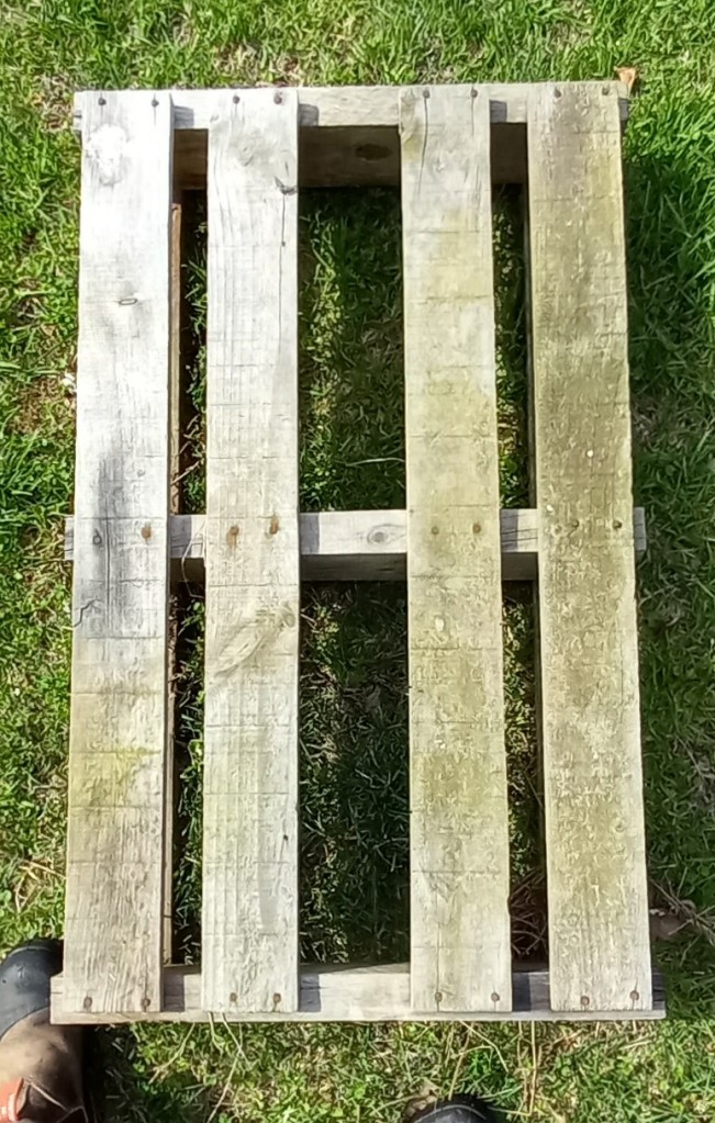
One item that was removed from the online order was pallets. They are simple items which are easy to assemble and at nearly no cost except time. We have plenty of pallets pass through the farm, so getting the relevant dimensions was easy. As an aside, pallets ain’t pallets – while the overall dimensions have been standardised (nominally 1180 x 1150 +/- 20mm based on a survey of pallets on our farm), they can be made from hardwood, softwood, or pine, and the number and size of battens, etc can vary. Pallets also get damaged, such as having broken, split and missing battens, and repairs create yet more variety. Pallets tend to go out of square as they age, and the fasteners loosen.
Top side of a hardwood pallet which has done a lot of work. Rails are 90x50mm and battens are 20mm thick.This heavy-duty pallet has clearly had a tough life. Made of softwood, the rails are 100x65mm and the battens are 30mm thick. Note the additional length of timber inside the left rail as a ‘running repair’.Bottom side of a relatively new softwood pallet. 90x50mm rails and 25mm battens.There are even half-size pallets. This pallet is made of pine and was probably meant to be used once. It carried a set of chain harrows weighing 250-300kg.
I recall reading that pallet sizes vary across the world. That certainly is the case in model form, eg Woodland Scenics pallets are rectangular compared to the near-square pallets in Australia. As far as I am aware, commercial models are either cast (plastic, white metal or resin), or 3D-printed, all of which then need to be painted to look like wood. I find it much easier to use wood.
I’m not sure how many pallets I will need (or want) but I expect between ten and twenty. That calls for a jig. So, the first task was to make a simple arrangement that holds the basic frame square while the glue hardens.
The jig. On the right-hand side is a pair of wedges used to hold the components square while the glue is drying. The outer wedge is fixed, while the inner wedge slides in and out. Scale 6×1″ end battens glued to scale 4×2″ rails. (Actually, the rails are 13.8mm and the battens 13.3mm.)Top side of 6×1″ ends with 4×1″ battens.Some finished pallets stained with a mix of India ink in isopropanol.
I assembled ten pallets in about an hour, then set them aside to dry overnight. They were then stained with a mix of India ink in isopropanol. Most prototype pallets are not painted but a couple of producers do colour theirs, so some of the models may get dry-brushed blue or maroon.
Although the Burrawon layout is not yet complete, the scenery and structures are in place and the layout is operational. Having reached that point, I have come to the realisation that I get most satisfaction from planning, building and constructing scenery and structures. There is no more room to physically expand the layout, save building another level perhaps, and that’s not a consideration at this point. However, I do have room under the layout where I could mount a diorama or two.
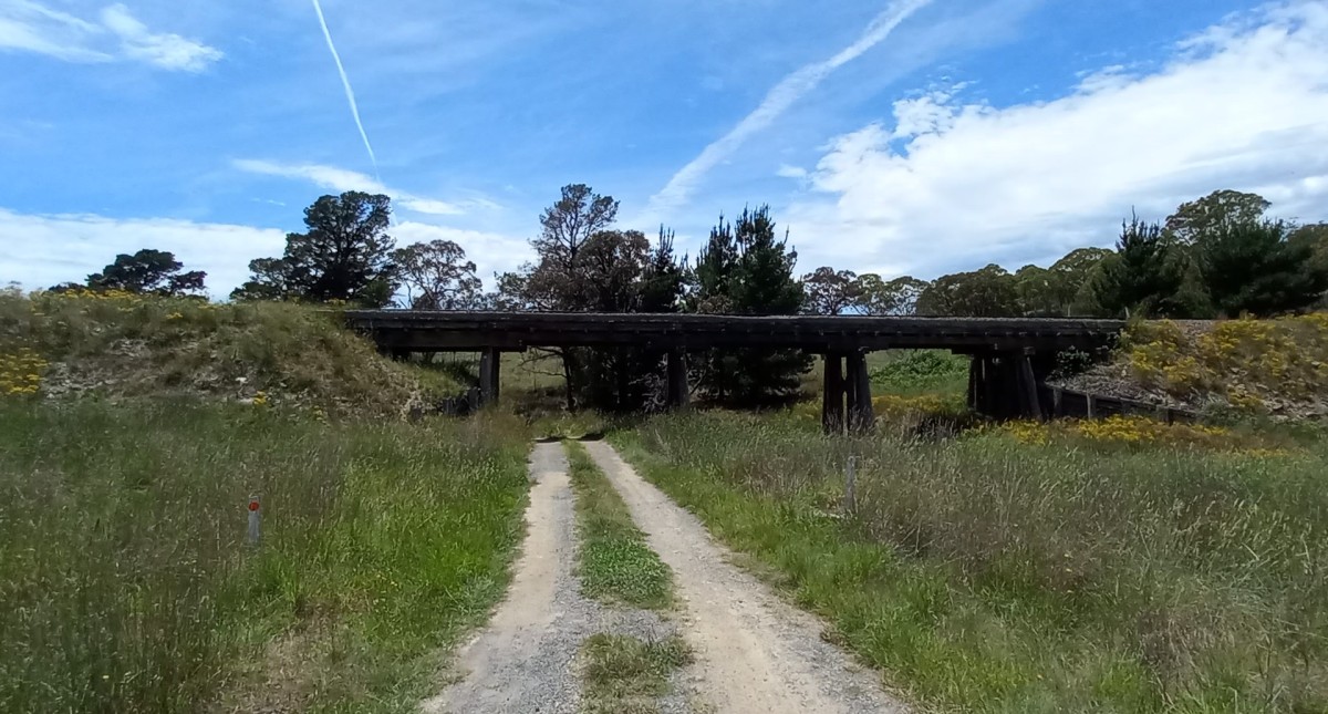
There’s something about timber trestle bridges that just grabs me and every layout I have built has had at least one trestle bridge. However, those bridges have not been accurate models of an actual bridge. Thus, I plan to build a diorama featuring a detailed, accurate model of a railway bridge (and I mean a bolt-counting accurate model). I have several candidates in mind, including the bridge near which I spent so much time watching trains in my youth (I have even bought a QR loco specifically for that project). However, that bridge will have to wait until I visit there again sometime in the future when I can take photos and measurements and grab a handful of the unique red soil there. In the meantime, my attention is on the bridge below. I visited it yesterday to do a preliminary reconnaissance and to assess the modelling potential of this structure. There’s not much else in the vicinity, but I think it’s big enough and interesting enough to be the subject of a diorama. It will certainly challenge my ability to construct a detailed model.
The subject, not centred in frame, just as I envision the model. The truth is that the glare was so great that I couldn’t see the image on the camera screen so, as with most of my photos, it was a case of point and shoot. Good enough for assessing the structure’s potential as a diorama subject.Bolt-counting might take some time when the detailed survey is undertaken.Likewise counting deck planks and all those other pieces of timber (and will I include bolt holes that previously had bolts??)The other side with the sun to my back and a large brown snake having just disappeared somewhere to my left. This view is helping me envision the orientation of the bridge on the diorama.
The next step will be a re-visit, armed with tape measure, ruler, camera, etc to undertake a thorough survey. However, I may wait until it’s a little cooler and the snakes are less active. I think I’ll invite an assistant too. Oh, and include a snakebite bandage and splints. You can never be too prepared or careful.
Modelling in a small space: developing a mini diorama.
Years ago, while driving along the Newell Highway, I espied a silo off in the distance. Having some time to spare, I decided to take a closer look. The location was Ardlethan. Around the same time, I had purchased one of Auscision’s ready-built resin silos so I hoped a visit to an actual silo might help me set the model convincingly on the layout I was building. However, at that time, I didn’t have a clear vision of how the model was going to sit in the scenery, so I didn’t really know what I was looking for. As a result, I took a few ‘general’ photos of the silo and surrounds – more ‘tourist’ shots than detail photos. I don’t recall gaining much insight at the time or even referring to the photos I had taken. It was probably too early in that layout’s scenic development.
Ardlethan silo (my photo 21/02/2009).
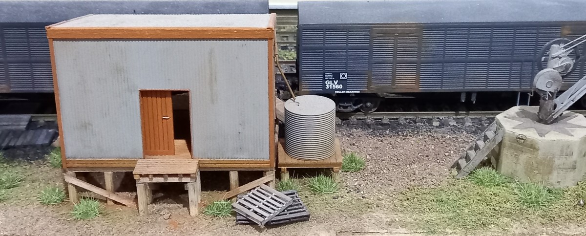
A decade later, and with very different modelling priorities, I revisited those photos when it came time to place the silo at Burrawon. This time, I knew I wanted the silo to be part of a mini diorama rather than just a large structure parked beside a siding. So, I used the block-built structure and the corrugated iron-clad dunny in the photos to guide construction of models for Burrawon. The nearby bushland in the photos also helped my thinking about how to disguise the model’s proximity to the backscene.
End view of the block-built structure. Window spaces blocked in. Note the corrugated dunny. (my photo: 21/02/2009)Ardlethan silo and surrounds. Three-quarter view of the block-built structure. (My photo: 21/02/2009)
I estimated the key dimensions for the building from the above photos by assuming the door in the end wall was standard size. I first built a cardboard mock-up to assess how the building would fit in the available space. It was too large for the space both physically and visually, so I reduced its width and length while maintaining the same roof pitch and wall height. Once satisfied, I scribed .030″ styrene sheet to simulate blockwork walls and ends. Unlike in the photo, I modelled the building with extant windows and doors. However, given the overall reduction, I cut just one window into the end wall. Corrugated styrene was used for the roof, with scale styrene strip for window, door and roof trims. Gutters are 2mm styrene channel with downpipes of .040″ brass rod. The structure was given a few coats of aged concrete, and the doors and trims were painted medium grey. A light dusting with earth tone weathering powders completed the model. Given the building’s proximity to the silo road, I added a safety fence between the two. The fence rail is code 83 bullhead soldered to code 100 flat-bottom rail posts. That fence also provides a visual buffer between the detailed elements of the diorama and the 3D/2D transition at the backscene.
Completed block-built shed and rail fence in situ.
The dunny is constructed of corrugated styrene, sprayed metallic grey and lightly weathered. The actual structure appeared to be in good repair even in 2009. For a bit of fun, I bent and painted a length of craft wire to resemble a red-bellied snake slithering into the dunny. I have encountered a few pythons (usually in the rafters) while using outdoor facilities in my time. I loathe pythons, but don’t mind red-bellies.
Dunny with snake slithering through the door.
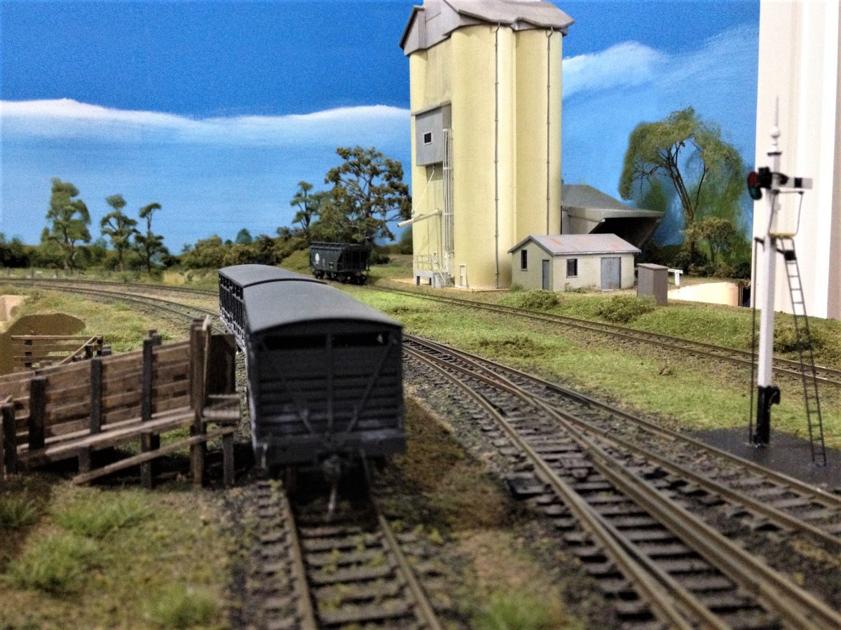
On the other side of the silo, I used a hand-made feature tree as a visual counterpoint to the silo within the mini-diorama, along with denser bushland near the end of the siding to disguise proximity to the backscene and to suggest that the siding is longer than what can be seen. The access road and pathway are sifted fine real dirt held in place with scenic cement.
A hand-made feature tree as a counterpoint to the silo also partially hides the access road and 3D/2D transition. Note the light green static grass between the rails under the loading chute representing sprouts from spilled grain.Trees, bushes and low scrub conceal the actual end of the siding, giving the impression that it goes further. The larger trees behind the siding also deflect attention from the backscene corner.This large tree is a feature of the Ardlethan yard area. This was the inspiration for using the large feature tree near the silo at Burrawon. While I didn’t make a model of this tree for the silo diorama, I did place a model of it elsewhere at Burrawon.
There’s still a couple of items to add, such as the power poles and some general clutter. The silo also would benefit from a bit more weathering. Overall, I am pleased with the result and how it works within the full Burrawon diorama.
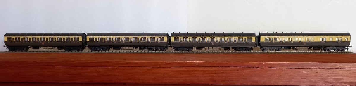
These 2mm finescale coaches are part of a rake of ten that I built in the mid-1980’s. They are based on etches that I commissioned from the original 3mm scale artwork by the late Stewart Hine. He photo-reduced the artwork to 2mm scale for etching. The etching firm required a minimum number to make the process cost-effective, so the extra units went to the 2mm Scale Association shop.
The floor, ends and sides are one etched piece. Tumblehomes were rolled into the sides and ends before they were folded and soldered into position. Underfloor details were fabricated from brass sheet and rod. I used styrene and clear acetate for the compartment and corridor walls. Seats and seat backs are styrene painted the appropriate upholstery colour for each compartment class. The distinctive grab handles aside each door are brass wire folded to shape. I made a small jig to fabricate them as there are more than 150 handles across the ten coaches.
All-third, corridor side.
The separate roof etch was rolled to the profile of the coach ends. The roof vents are white metal castings. The roof was glued to the body after everything had been painted. The underframe, body and roof were airbrushed. The door droplight frames were hand-painted. The GWR crests are 2mm Scale Association decals. The class lettering and coach numbers in the waistline moldings are hand-painted (more depiction than actual lettering).
GWR 57′ brake-third, corridor coach. Corridor side. The interior detail – compartment and corridor walls and seat backs can be seen.
The wheels and the etched brass compensated bogie kits are 2mm Scale Association products, as are the resin side-frame castings glued to the bogies. I hand-turned the buffers and shafts. I sprung the buffers by using a strip of acetate behind the buffer beams. The coaches were coupled using three-link couplings that I fabricated from thin copper wire. I was never able to produce a convincing screw coupling that worked effectively.
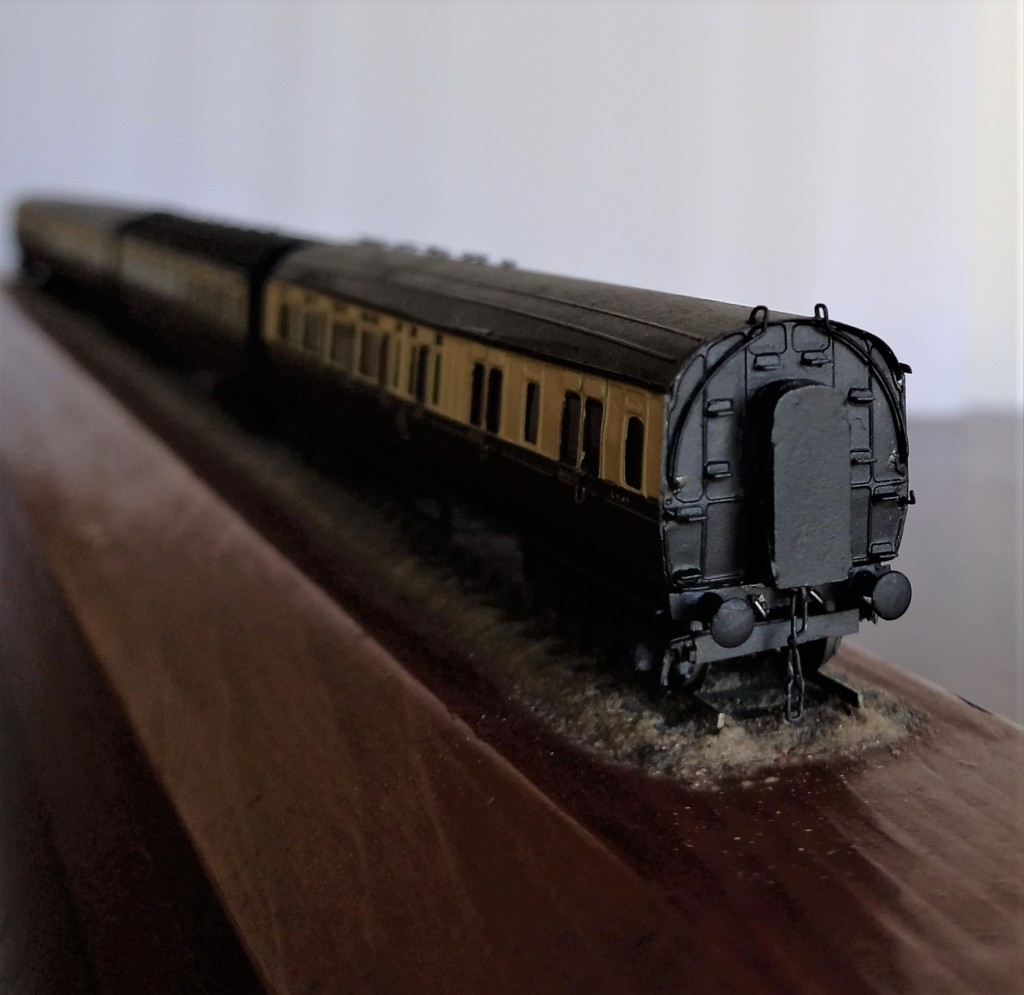
Brake-third, compartment side.
I don’t remember too much about constructing these, but I do remember being able to mount them on the track fairly easily back in the day – unlike how long it took me in 2023. The eyes and dexterity aren’t what they used to be -sigh!
Tail-end of the brake-third. Curved handrails of phosphor-bronze wire. Individual steps soldered to the end wall. Cast white metal corridor connection. Hand-turned sprung buffers. Scratch-built three-link coupling – screw couplings were used on coaching stock, but I was never able to produce a reliable model.
I started building these coaches while I was building a scale model of Brent station on the GWR main line in South Devon. Brent was the junction for the Kingsbridge branch, which on the layout ran into a fiddle yard. The layout occupied a 6×3.5m garage. I had hand-built and laid all the track (9.42mm gauge) and scenic development was underway when we moved house. The layout did not come. Instead, I began a scale model of Gara Bridge, the passing station on the Kingsbridge branch. The layout was 6m long with reversible sector plates at each end. The Kingsbridge branch used small prairie tank locos and just a few passenger coaches, so a rake of ten coaches was a touch of overkill, except, perhaps, for a double-headed summer holiday special.
I built Gara Bridge to be portable, so it came with us when we relocated from Brisbane to Townsville in 1995 and several house moves while there. In the late 1990’s my sons became interested in model trains, so I built an HO layout for them. Austrains had recently released their NSWGR 80 class diesel loco which I purchased, purely on a whim, and was so impressed with its running quality, that the GWR in 2mm was reluctantly abandoned. Gara Bridge did not come when we moved to Sydney in 2008, but I did keep all the stock that I had built. The few photos I had of the Brent and Gara Bridge layouts were lost as result of the Black Summer fires – not to fire but, ironically, to water damage (rain).
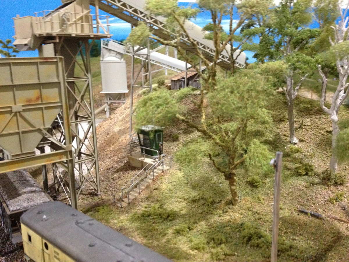
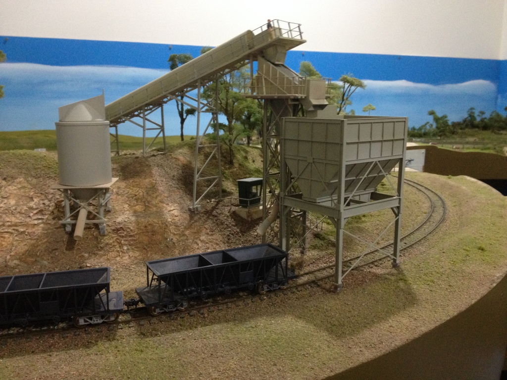
At the time I built the cylindrical hopper for One Mile quarry I envisaged modelling it as abandoned – rusting and with just remnants of its conveyor. However, as part of the quarry site revision, I decided to model it in use. That involved moving the hopper further from the main loader. The SixMaps image of Martins Creek quarry shows it to be about four hopper-lengths from the main loader. Briefly, the model is a length of 50mm diameter PVC pipe to which scratch-built conical top and bottom sections and other trimmings have been added. The additions were fabricated from thin styrene sheet and strip.
The cylindrical hopper was inspired by one in the background of the photo I used to make the loader and associated structures. The SixMaps image of the prototype suggests that there is about four ballast wagon-lengths between the loader and the hopper.Cylindrical hopper in its new position. The arrangement of other elements of the revised diorama is being assessed.
The next task was to build a conveyor for the hopper. I made it in the same way as the main conveyor (March 6, 2021), using Plastruct Warren Truss pieces as the conveyor frames. Lengths of styrene strip were used as frame supports and spacers. A length of styrene sheet was glued inside the structure to represent the conveyor belt.
Conveyor frame: Plastruct Warren truss side frames, styrene sheet and strip details.Canopy of .010″ styrene sheet. The styrene sheet was warmed with a hairdryer while being rolled around a 12mm diameter dowel. It was then glued to the frame.
The header and deck were next. These are made of styrene strip and sheet. I drilled holes in the deck frames for the handrails to be added later. It was then glued to the conveyor. Two bents, made of styrene strip, I-beam, and H-column pieces were assembled to support the structure. These were glued to the structure after the handrails had been fitted.
Test fitting the header deck. Constructed of styrene strip. Open areas will be covered with etched brass mesh.Site test. The two bents will be glued to the conveyor after the handrails are fitted to the deck and gangway.Bending the header deck railings around 3mm dowels to give 1.5mm radius corners. Test fitting the header deck railings before they are trimmed and cleaned. Railings are .015″ phosphor-bronze, posts are .020″ brass. Deck mesh to be fitted before the railings are secured in place.Unpainted conveyor in place.The conveyor painted but not yet weathered. Plenty of scenic development to be undertaken before weathering all the structures into the scene.The conveyor in position on the hopper. I particularly like this view of the new conveyor framed by the first conveyor.