Point rodding – when is the best time to add it?

Modelling in a small space: adding point rodding at Tarawangan.

I have begun installing point rodding and associated infrastructure at Tarawangan. I’m not sure that there is an ideal time during a layout’s development for undertaking this task. If it’s done relatively early there is the risk of damaging the rodding and fittings as other work progresses. There is also the risk early on, as trains are run, that changes to the track arrangement become necessary. That was certainly the case at Tarawangan which had three significant track adjustments in the first year or so. Let’s also be honest: it is both a daunting and a tedious task.

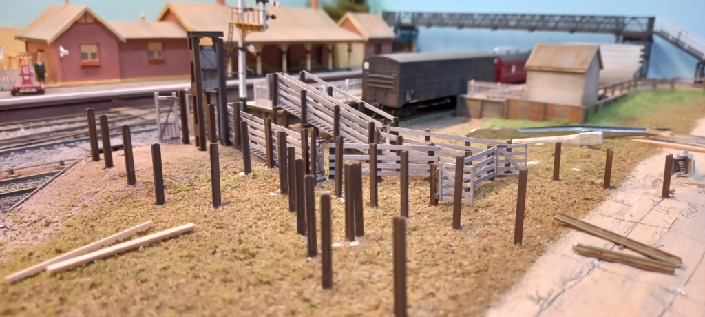
I decided early on that I would add rodding after completing the majority of the scenic work. However, this approach is not without drawbacks; the greatest of which is having to disturb existing scenery in order to position particular details. Sometimes, drilling a small hole is all that is required. At other times, scenic material may need to be removed. This can be relatively minor, such as setting point rodding chairs, compensators, cranks, etc in place; or more extreme, such as cutting a hole into the baseboard to locate a signal. The risk, then, is of damaging the scenic shell more widely. There is also the issue of matching new work with existing scenery.

Some time ago, I added a lever frame and rodding in the Tarawangan yard. For this, I used components from the Anton’s Trains range. Sadly, with just single and double roller chairs available, that range is limited to yard settings.

Lever frame, cranks, compensator, rodding and indicator for the cross-over from yard loop to branch line. I removed small squares of ground cover so that each chair could be set onto the baseboard, then backfilled with fine dirt and over-sprayed with dirty grey. Despite that, the new work is still visible, but tolerable.

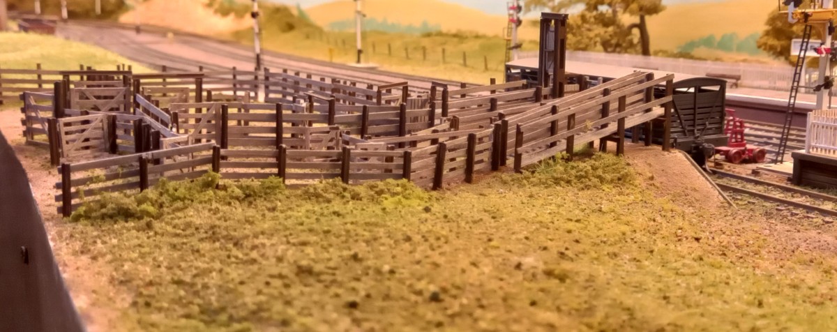
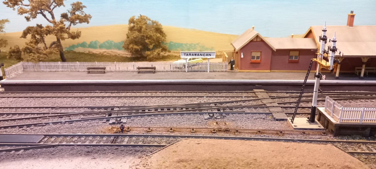
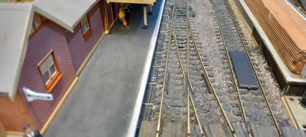
The track arrangement elsewhere at Tarawangan requires rodding runs of up to eight chairs across. Fortunately, Andian Models 3D-printed sets of 1, 2, 3 and 4 chairs. They are very fine representations too. Being resin, they can be easily adjusted to make chair sets of greater numbers – in my case, up to 8 wide. In the absence of alternatives, but also for consistency, Anton’s cranks and compensators are used. To get a feel for working with the Andian chairs and rodding, I began with a short run of 4-chair and 2-chair sets for the double slip on the down main and the loading dock catchpoint and indicator. I couldn’t get good reach and sight along the rail-side of the down platform to set chairs there and thread the rodding (another disadvantage of adding rodding later than earlier), so the fiction is that the platform signal box is beyond the footbridge (ie off-scene) and the shortest, straightest run is under the down platform and out beside the bracket signal.

Test-positioning angle cranks for the double slip and catchpoint prior to disturbing the groundwork.
Ground cover removed to expose baseboard along the rodding path. Bases of 2 x 3.2mm styrene support the roller stands and cranks. The bases are sufficient to raise the rodding to near rail height.
Medium stones used to backfill around the bases (painted dark earth). Fine dirt and cinders will complete the ground cover.
Ground work completed and sprayed dirty grey. Roller chairs, cranks and rodding fixed in place. Just need to paint the rodding dark rust.

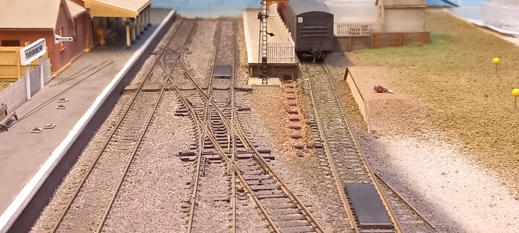
In hindsight, I should have reversed the rodding order so that the cranks were under the rodding more. If nothing else, the final result would have appeared neater. That said, the overall result is visually satisfactory. Working each rod through each roller chair is tedious but is eased by running a no 77 drill through each hole before fixing the chairs in place.

Rodding painted dark rust. Rust and dirt weathering powders dusted around bases and rodding – that will tone down with a misting of water.
From the usual viewing position.
And a board ramp over the rods.

So, in for a penny, in for a pound! Work has begun on the mainline run.

Eight rods in position, yet to be painted and weathered.
Rods beyond the board crossing have been painted. This side of the crossing chairs are in place and some rodding fitted.

More to follow.

Tarawangan Trucking Yard

Modelling in a small space: Tarawangan trucking yard completed.

This project has been time-consuming and challenging but, ultimately, I am satisfied with the result. I relied heavily on Stephen Ottaway’s comprehensive review of prototype trucking yards in the Australian Journal of Railway Modelling, issue 13. I recommend it to anyone considering building a model. This is the first project that I have recorded from start to finish in parallel with construction. https://youtu.be/775mHW6Cj7k

A new scratchbuilding project

Modelling in a small space: a trucking yard for Tarawangan

The Tarawangan crew has begun work on a trucking yard. Early activity has centred on fabricating stock races and associated furniture. Nothing yet set in place – just stacking items as fabricated. More to follow.

Upper sheep race and working platform on right. Cattle race and lower sheep ramp in centre. Limit of unloading bank on left.

A new motor for 4405.

Finding and fitting a replacement motor to a Trainorama 44class loco.

My Trainorama 4405 suffered a catastrophic motor failure recently. What is particularly bewildering is that there was no warning. After working the last train of the day’s running session, 4405 eased onto its storage road smoothly and silently – as always. The very next running session, it required twice as much throttle to get it to move at all, and then, very roughly and anything but silently! How does an engine go from perfect to an absolute dog overnight??

My first thought was that an axle muff gear was slipping – despite having replaced all muff gears eighteen months previously. Besides, usually when a muff gear fails there is an extended period of gradually worsening running and with increasing noise – specifically a clicking sound. The sound emanating from 4405 this time was a metallic graunching. Nonetheless, I first checked, then lubricated the gear train on each bogie which yielded no improvement in running or reduced noise. Thus, I completely dismantled the loco in order to remove the motor. The motor was rough to turn by hand – not a good sign – and equally rough and noisy when connected to power. That suggests something has come adrift within the motor, although I could not hear anything rattling around. There was about 5mm fore/aft movement in the drive shaft which seemed excessive to me. With no way to get inside the motor (the flywheels were firmly attached to the driveshaft) I will never know whether some component came adrift or if a bearing failed. That’s all pretty academic, as I won’t use that motor again regardless of the issue.

So, the search began for a suitable replacement. The Trainorama site doesn’t list spare motors, nor did they respond to my query, so that was a dead-end. A few other model shops listed motors of the same or similar dimensions as the failed one but, sadly, did not have flywheels and universal sockets fitted. Auscision have replacement motors for their 44 class, which look very similar to the Trainorama motor and are fitted with twin flywheels and universal sockets. Motor ordered.

The Auscision motor is a little wider, and the length over the drive shaft (including universal sockets and flywheels) is slightly longer (2.8mm). I modified the original motor cradle to accommodate the new motor’s power tabs. As the new motor has no screw holes to secure the motor to the cradle, I used a length of double-sided tape to hold the motor to the cradle. I replaced the Auscision feed wires with the original wires.

Left: original motor.       Right: replacement motor (2.8mm longer overall).
Trainorama motor cradle modified to hold Auscision motor. Centre hole opened out to 7.5mm diameter. Top right mounting screw hole opened to clear power feed tab (same for bottom left not yet done).
Motor in cradle. Feed cables yet to be replaced with those from the loco.

The longer overall length of the new motor reduced the free travel for each drive shaft to about 1.0mm which I felt was a bit tight. To play it safe, I fabricated replacement drive shafts from brass tube and phosphor-bronze rod, so that each shaft’s free travel was again about 2.5mm.

Fabricated driveshafts of brass tube and phosphor-bronze rod. Brass on brass is not the best combo, according to machinists, but I suspect it will see me out. One is 1mm shorter than the other reflecting the fact that the new motor is slightly closer to one bogie than the other. These shafts yield about 2.5mm free play between motor and bogie.

Complete reassembly went without a hitch and the loco runs smoothly and quietly again.

Back on the rails and ready for work.

A tour of Burrawon station precinct

Modelling in a small space: a look at the scenes that contribute to the Burrawon diorama.

This short video outlines the mini scenes that contribute to the Burrawon station diorama. The key aim of the diorama is to convey the sense of space that is typical of rural settings. The scenery, structures and details within each scene are described. As an aside, the layout may be set in the early 1980’s, and it may still use DC, but that doesn’t mean that everything Burrawon is so 20th century. Recent concessions to the 21st century include adopting JMRI OperationsPro to generate train consists for operating sessions and, in the case of this video, embracing text to voice technology.

An addition to the wagon roster

Heavy weathering for an On-Track Models LLV before entering service.

This On-Track Models LLV had the candy stripe livery. I find that livery especially jarring on goods stock, so the wagon wasn’t going onto the layout until repainted. I had already repainted and weathered another candy LLV some time back (Miscellany, 13 August 2022). So far back, in fact, that I forgot exactly what I did. To add insult to injury, I had run out of my favourite brand of rust paint (now no longer available). More about that later. I was inspired by a 1986 photo of a weather-worn LLV 10001 on the NSW Goods Rollingstock site (http://www.nswgoodsrollingstock.com/LLV.htm). 

My aim was to give the model an overall patina of surface rust with occasional patches of deeper rust. I began by spraying a coat of white primer over the existing paintwork. Then, the underbody and bogies were sprayed with weathered black and the body was sprayed dark grey. This was followed with my own version of medium rust using chrome yellow, dark brown and a touch of poster red. After applying the decals, the van was sprayed with flat clear.

Medium rust air-brushed unevenly over sides, ends and roof- a bit too much, but I had a plan!

The following day I brushed a thin wash of dark grey acrylic paint into the louvre grooves. In hindsight, a black-brown wash may have worked better. I then wiped a damp sponge across the body to remove excess wash from the louvre surfaces. Then, a sponge was used to dab varying shades of rust randomly on the sides, ends and roof, after which a dry, stiff-bristled, flat brush was drawn across the damp paint. Once everything was touch dry, the same brush was dragged along the louvres to clear any stray paint dabs from the grooves. A final coat of flat clear completed the job.

LLV 2386 brake reservoir side.
Triple valve side.

I’m satisfied with the overall result, although it took longer than expected to achieve what I envisioned.

Looking a little unloved but ready for work nonetheless.

Last grain train

Modelling in a small space: a snippet from an operating session.

Locomotive 4405 is at Burrawon to collect the last grain train of the harvest season. The consignment of seeding grain has been loaded into grain hoppers and repurposed fertiliser hoppers. After drawing the train off the silo siding, the loco runs round the train and then departs. There’s even time to take in some sights around the yard and surrounds while the loco goes about its business.

A palette of pallets

An easy to make detail item.

After assembling a list of detail items for the layout, I went online to place an order. I was taken aback at how fast and big the total grew, so I reviewed what I really needed vs what I wanted and trimmed the order. Nonetheless, the bill for what are minor detail items got me thinking about what I can reasonably make vs what I cannot. In truth, I prefer to make as much as I can because I enjoy scratchbuilding, and I have the time. Also, I can maintain a fairly uniform ‘standard’ of models on the layout which I think helps a layout look more convincing. Another reason I choose to scratchbuild is that I can use scale lumber for wooden items, and I prefer using wood to model wood.

One item that was removed from the online order was pallets. They are simple items which are easy to assemble and at nearly no cost except time. We have plenty of pallets pass through the farm, so getting the relevant dimensions was easy. As an aside, pallets ain’t pallets – while the overall dimensions have been standardised (nominally 1180 x 1150 +/- 20mm based on a survey of pallets on our farm), they can be made from hardwood, softwood, or pine, and the number and size of battens, etc can vary. Pallets also get damaged, such as having broken, split and missing battens, and repairs create yet more variety. Pallets tend to go out of square as they age, and the fasteners loosen.

Top side of a hardwood pallet which has done a lot of work. Rails are 90x50mm and battens are 20mm thick.
This heavy-duty pallet has clearly had a tough life. Made of softwood, the rails are 100x65mm and the battens are 30mm thick. Note the additional length of timber inside the left rail as a ‘running repair’.
Bottom side of a relatively new softwood pallet. 90x50mm rails and 25mm battens.
There are even half-size pallets. This pallet is made of pine and was probably meant to be used once. It carried a set of chain harrows weighing 250-300kg.

I recall reading that pallet sizes vary across the world. That certainly is the case in model form, eg Woodland Scenics pallets are rectangular compared to the near-square pallets in Australia. As far as I am aware, commercial models are either cast (plastic, white metal or resin), or 3D-printed, all of which then need to be painted to look like wood. I find it much easier to use wood.

I’m not sure how many pallets I will need (or want) but I expect between ten and twenty. That calls for a jig. So, the first task was to make a simple arrangement that holds the basic frame square while the glue hardens.

The jig. On the right-hand side is a pair of wedges used to hold the components square while the glue is drying. The outer wedge is fixed, while the inner wedge slides in and out. Scale 6×1″ end battens glued to scale 4×2″ rails. (Actually, the rails are 13.8mm and the battens 13.3mm.)
Top side of 6×1″ ends with 4×1″ battens.
Some finished pallets stained with a mix of India ink in isopropanol.

I assembled ten pallets in about an hour, then set them aside to dry overnight. They were then stained with a mix of India ink in isopropanol. Most prototype pallets are not painted but a couple of producers do colour theirs, so some of the models may get dry-brushed blue or maroon.

Design a site like this with WordPress.com
Get started