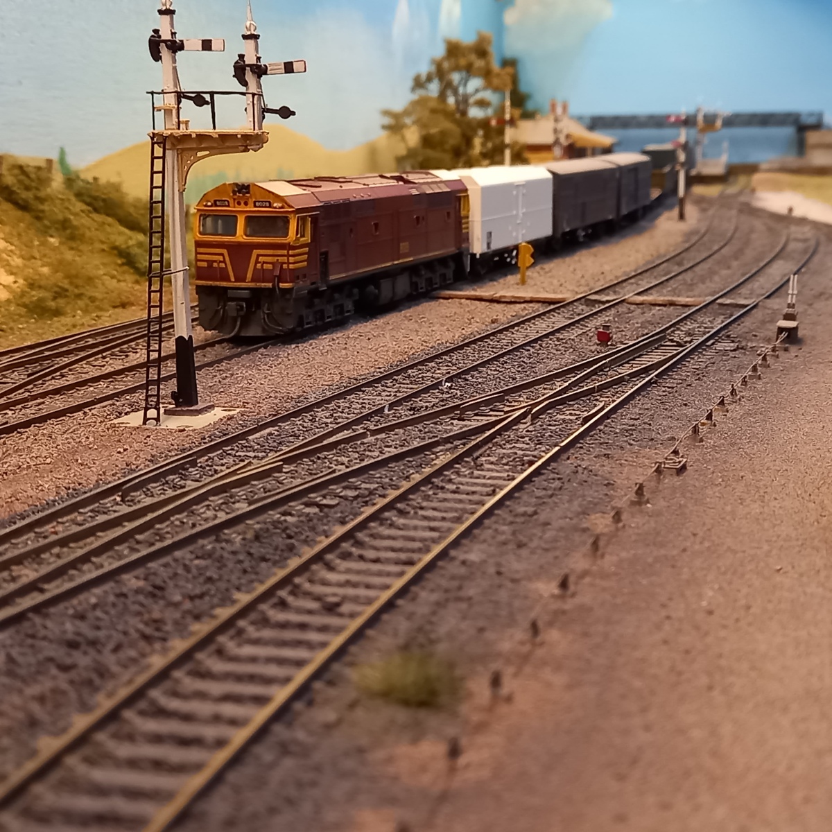
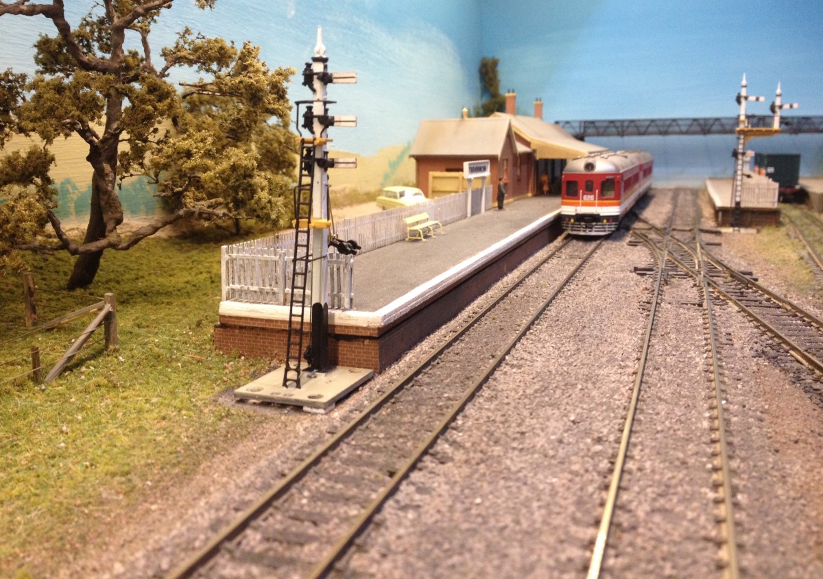
Point rodding – when is the best time to add it?

Modelling in a small space: adding point rodding at Tarawangan.

I have begun installing point rodding and associated infrastructure at Tarawangan. I’m not sure that there is an ideal time during a layout’s development for undertaking this task. If it’s done relatively early there is the risk of damaging the rodding and fittings as other work progresses. There is also the risk early on, as trains are run, that changes to the track arrangement become necessary. That was certainly the case at Tarawangan which had three significant track adjustments in the first year or so. Let’s also be honest: it is both a daunting and a tedious task.

I decided early on that I would add rodding after completing the majority of the scenic work. However, this approach is not without drawbacks; the greatest of which is having to disturb existing scenery in order to position particular details. Sometimes, drilling a small hole is all that is required. At other times, scenic material may need to be removed. This can be relatively minor, such as setting point rodding chairs, compensators, cranks, etc in place; or more extreme, such as cutting a hole into the baseboard to locate a signal. The risk, then, is of damaging the scenic shell more widely. There is also the issue of matching new work with existing scenery.

Some time ago, I added a lever frame and rodding in the Tarawangan yard. For this, I used components from the Anton’s Trains range. Sadly, with just single and double roller chairs available, that range is limited to yard settings.

Lever frame, cranks, compensator, rodding and indicator for the cross-over from yard loop to branch line. I removed small squares of ground cover so that each chair could be set onto the baseboard, then backfilled with fine dirt and over-sprayed with dirty grey. Despite that, the new work is still visible, but tolerable.

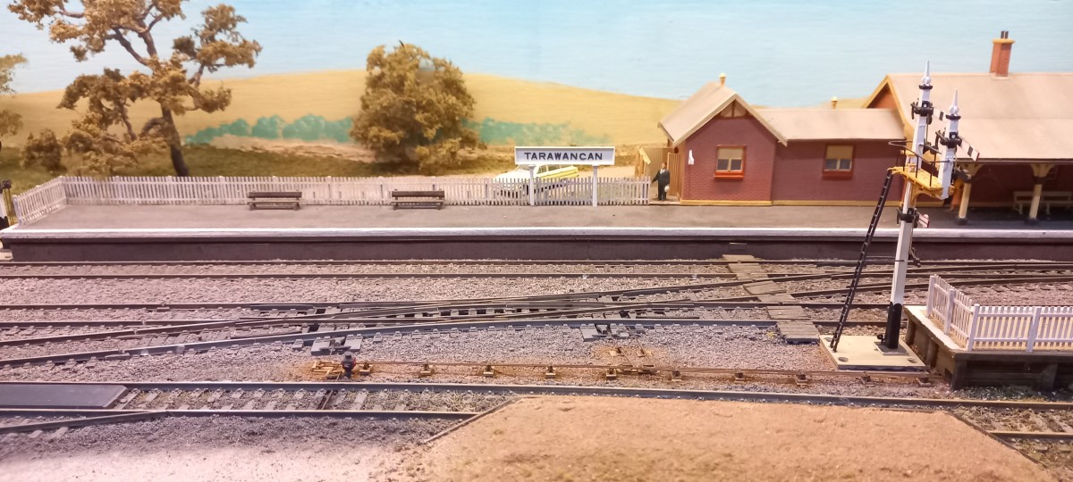
The track arrangement elsewhere at Tarawangan requires rodding runs of up to eight chairs across. Fortunately, Andian Models 3D-printed sets of 1, 2, 3 and 4 chairs. They are very fine representations too. Being resin, they can be easily adjusted to make chair sets of greater numbers – in my case, up to 8 wide. In the absence of alternatives, but also for consistency, Anton’s cranks and compensators are used. To get a feel for working with the Andian chairs and rodding, I began with a short run of 4-chair and 2-chair sets for the double slip on the down main and the loading dock catchpoint and indicator. I couldn’t get good reach and sight along the rail-side of the down platform to set chairs there and thread the rodding (another disadvantage of adding rodding later than earlier), so the fiction is that the platform signal box is beyond the footbridge (ie off-scene) and the shortest, straightest run is under the down platform and out beside the bracket signal.

Test-positioning angle cranks for the double slip and catchpoint prior to disturbing the groundwork.
Ground cover removed to expose baseboard along the rodding path. Bases of 2 x 3.2mm styrene support the roller stands and cranks. The bases are sufficient to raise the rodding to near rail height.
Medium stones used to backfill around the bases (painted dark earth). Fine dirt and cinders will complete the ground cover.
Ground work completed and sprayed dirty grey. Roller chairs, cranks and rodding fixed in place. Just need to paint the rodding dark rust.

In hindsight, I should have reversed the rodding order so that the cranks were under the rodding more. If nothing else, the final result would have appeared neater. That said, the overall result is visually satisfactory. Working each rod through each roller chair is tedious but is eased by running a no 77 drill through each hole before fixing the chairs in place.

Rodding painted dark rust. Rust and dirt weathering powders dusted around bases and rodding – that will tone down with a misting of water.
From the usual viewing position.
And a board ramp over the rods.

So, in for a penny, in for a pound! Work has begun on the mainline run.

Eight rods in position, yet to be painted and weathered.
Rods beyond the board crossing have been painted. This side of the crossing chairs are in place and some rodding fitted.

More to follow.
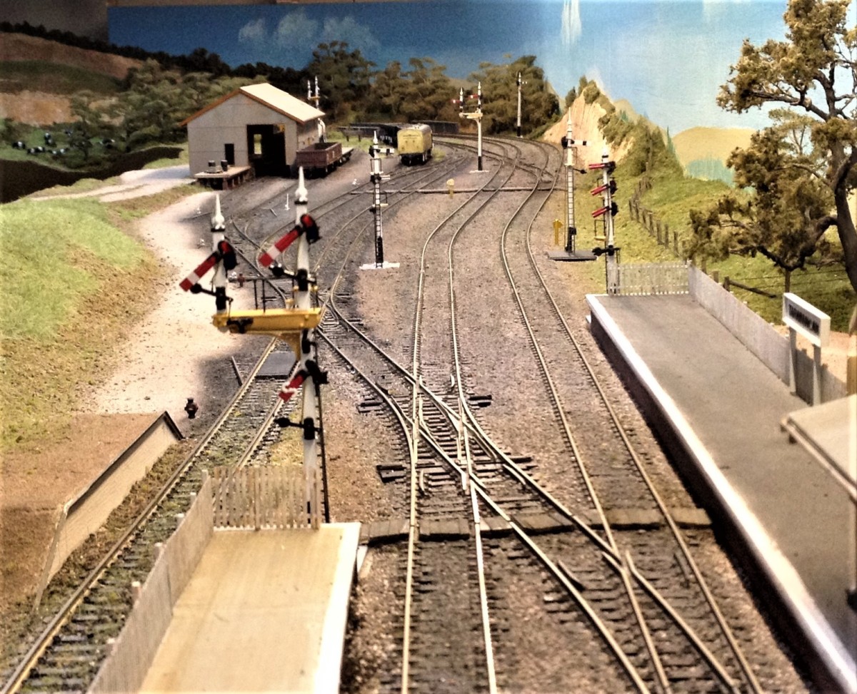
Tarawangan Trucking Yard

Modelling in a small space: Tarawangan trucking yard completed.

This project has been time-consuming and challenging but, ultimately, I am satisfied with the result. I relied heavily on Stephen Ottaway’s comprehensive review of prototype trucking yards in the Australian Journal of Railway Modelling, issue 13. I recommend it to anyone considering building a model. This is the first project that I have recorded from start to finish in parallel with construction. https://youtu.be/775mHW6Cj7k

A new scratchbuilding project

Modelling in a small space: a trucking yard for Tarawangan

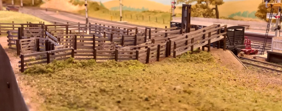
The Tarawangan crew has begun work on a trucking yard. Early activity has centred on fabricating stock races and associated furniture. Nothing yet set in place – just stacking items as fabricated. More to follow.

Upper sheep race and working platform on right. Cattle race and lower sheep ramp in centre. Limit of unloading bank on left.

Another signal adjustment

Modelling in a small space: relocating the UP branch signal for operational purposes.

UP trains leaving the branch can either continue directly onto the mainlines or enter the Tarawangan yard via a turnout that is controlled by a bracket signal. The signal also has a shunt ahead arm below the bracket that controls shunting movements along either route. I originally located the signal on the Burrawon side of the Little River bridge – somewhat distant from the turnout it protected. Operationally, that led to light engines needing to travel quite a distance beyond the turnout in order to clear the signal. I have rectified this by moving the signal closer to the turnout.

The UP branch signal in its original location, well before the turnout it protects (behind the tree).
The signal in its new location with the associated turnout just beyond: left road to the mainlines, right road into Tarawangan yard.
Light engine awaiting clearance to proceed. The original signal position required light engines to run across the bridge and further down the branch.

Groundwork was relatively straightforward. A new 22mm hole was cut into the baseboard and existing ground cover cleared away so that the signal base could sit neatly on the baseboard. Some static grass tufts, ground foam and fine leaf foliage were then added. The disused hole was plugged from below with a piece of card. The ground level was then built up with small stones. Large stones were placed along the branch line embankment before static grass, fine leaf foliage and assorted ground foams were added and secured with scenic glue.

Scenic work over the original site. Large stones along the embankment edge, static grass, fine leaf foliage and assorted ground foams.

All in all, a quite simple and quick process that improves operation, with the added benefit that the signal is now easier for operators to see.

A new signal at Tarawangan

Modelling in a small space: a signal to control down trains leaving the yard

I have long been bothered by the lack of signal protection at the down end of the Tarawangan yard where a direct link from the main lines merges with the branch line just outside the yard. Down trains exit the yard via the branch line which runs between the yard tracks and the down main. Additionally, trains working the yard sometimes shunt ahead onto the branch proper. Up trains in that area are protected by a bracket signal, including shunt arm. Likewise, trains taking the branch from the down main are controlled by a bracket signal. However, down branch trains and those shunting the yard have had no such protection to date. I have addressed the issue by installing a new signal.

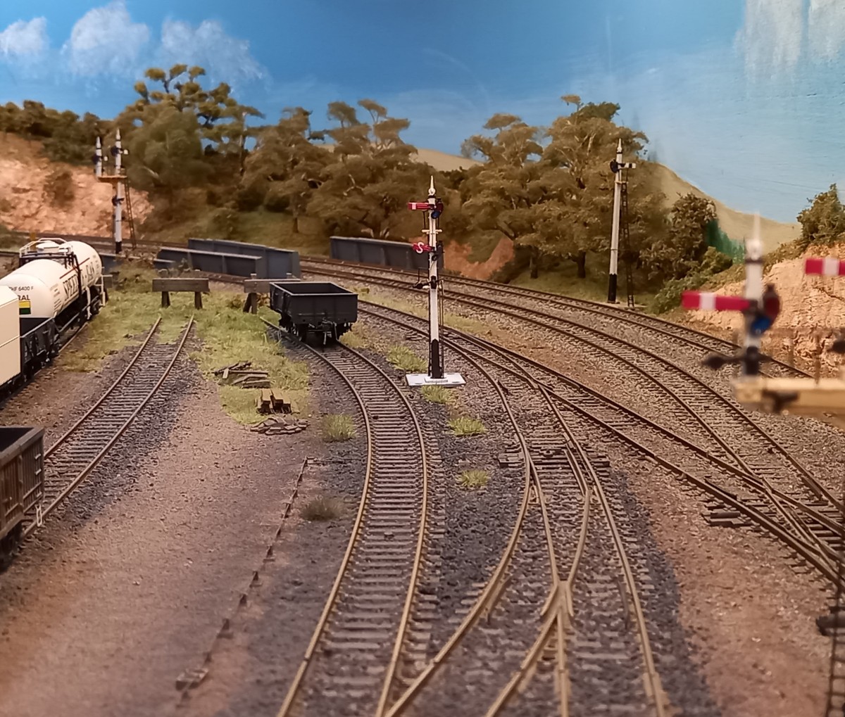
Down end of Tarawangan yard. Crossover between branch line and yard loop in foreground. Unprotected junction of branch line and direct connection with mainlines in midground. Trains from the down main entering the branch are controlled by a bracket signal, the arm of which is visible on the right.
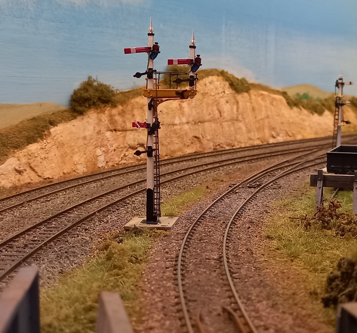
The bracket signal controlling UP branch trains. Left arm for main lines, right arm for branch/yard. Shunt ahead for shunting movements along either route.

The new signal is a Signals Branch 23′ timber post with 30″ starter and shunt ahead arms. Space is limited at the down end of the yard, so I placed the signal where the running line and adjacent siding reached a separation of 45mm between their adjacent rails. The signal’s linear servos are operated using a Railcon MD003 servo motor control module. Fully signalled operation on the layout is now possible.

The new signal in place, controlling entry onto the branch for down trains and shunting movements.

8028 heads the down pick-up goods

Having recently weathered 8028, I wanted to see it in action. So, here it is at the head of the down mainline pick-up goods, shunting the Tarawangan yard before making its way down the mainline. I have used a different editing program for this video which is more flexible and has more features than the one I have used previously. Lots of learning ahead.

The railcar on the main

This short video shows the branch railcar running up the main line to Tarawangan station where it stops before reversing down the line to take the branch line. The video features the signals that control the railcar’s path – a chance to demonstrate some operating signals. The outer home signal and the three-arm signal were each made by Ray Pilgrim (Signals Branch). I made the inner home signal from a Uneek kit. https://youtu.be/_ZsRa3CaRRQ

Tarawangan signals – 2

The last three signals for Tarawangan arrived a few weeks ago. Two are bracket signals, each with a shunt arm located below the bracket deck. One, located at the end of the down platform, is the down main starter and branch/yard entry. The other is located on the branch to control the junction with the main lines and entry into the yard (photo below). In each instance, the shunt arm permits shunting movements onto either the branch/yard or the main lines.

RH bracket for up branch trains running onto the main line (left arm) or entering Tarawangan yard (right arm). The shunt ahead arm under the bracket permits shunting on either line. (Photo: Ray Pilgrim)
Branch up bracket signal in place but not yet connected to the servo controllers. Tarawangan up main outer home signal in the background.


The third signal has three siding arms on the 23ft post. The three arms control movements from the up main: crossing from the up main to the down main; crossing the down main directly onto the branch (by-passing the yard); crossing the down main into the yard (including the branch line that runs through the yard). Tarana had a four arm signal at the down end of the up platform with three arms performing similar functions to the model, and the fourth arm for trains reversing into the up refuge siding.

Three siding arms on 23ft post, to be located at Tarawangan up platform down end, control moves off the up main, all of which are in the down direction. (Photo: Ray Pilgrim)

These three signals complete the signal requirements for the layout (16 arms). All, except the Tarawangan Up main home signal, have been constructed by Ray Pilgrim (Signals Branch). They look great and operate flawlessly. These signals required new elements which Ray had to design and fabricate. I thank him sincerely for the time he put into these tasks and his patient assistance and guidance. Although I have tried to follow prototype signalling practice as I understand it, this is an operating layout and the signals ultimately need to work in and for that setting. They most certainly look the part.

Each of the new signals has three linear servo’s. I had previously been using one Tam Valley Octo III servo controller to activate the servo’s and had devised a means for activating more than eight servo’s from it (Signals for Tarawangan, October 30, 2021). Sadly, Tam Valley stopped making the Octo III while restructuring. Fortunately, Sydney-based Railcon produce a servo controller that is suitable for points and signals (MD003). Each MD003 unit can control two servo’s. They are activated by SPST toggle switches and are easy to install and to fine-tune. I am now using these exclusively. As it has taken a few weeks to obtain the other items needed to get the signals operating I have taken the opportunity to plan a wiring arrangement that is organised and neat (unlike the other wiring under the layout). This has inspired me to adopt a similar procedure for all of the layout’s wiring – something that I plan to undertake in stages.

New signals in place. Left foreground: Down main starter/branch entry on bracket. Shunt ahead for either road. Right foreground: top arm for distant crossover onto down main; middle arm for distant crossing onto branch; bottom arm for crossover into yard/down main.

Post-script: Back in November, after the previous signals had arrived (post of October 30, 2021), I soon realised that two of them were not best located. So, after a couple of weeks’ deliberation and being sure that the new positions worked visually and operationally, I cut new holes and re-located the signals. The old holes were filled in and ground cover added.

The branch home/siding signal (front left) and the down main/branch bracket signal (centre left) as first located at Tarawangan.
The re-located signals from the down main platform (compare with the above photo from the same position). The increased distance between the two signals helps make the yard area appear longer both from this angle and from side-on.
Main/branch bracket signal in new position. White filler (right) is the previous position.
Re-positioned branch/siding signal. White filler (left) in the previous position.

Design a site like this with WordPress.com
Get started